First try! ... Kinda...
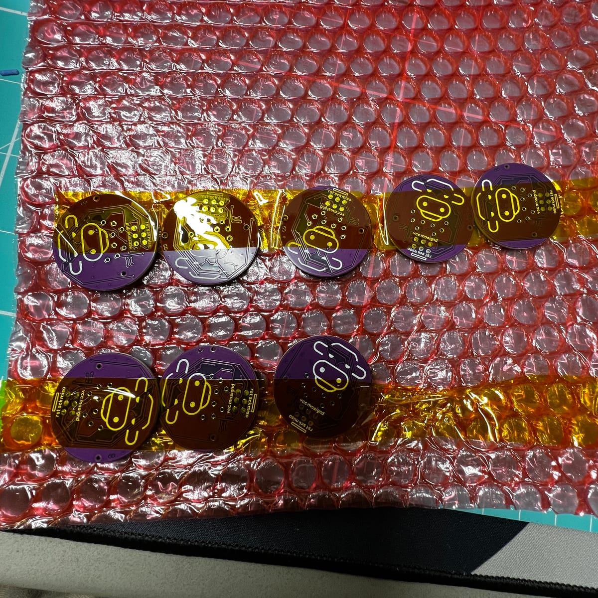
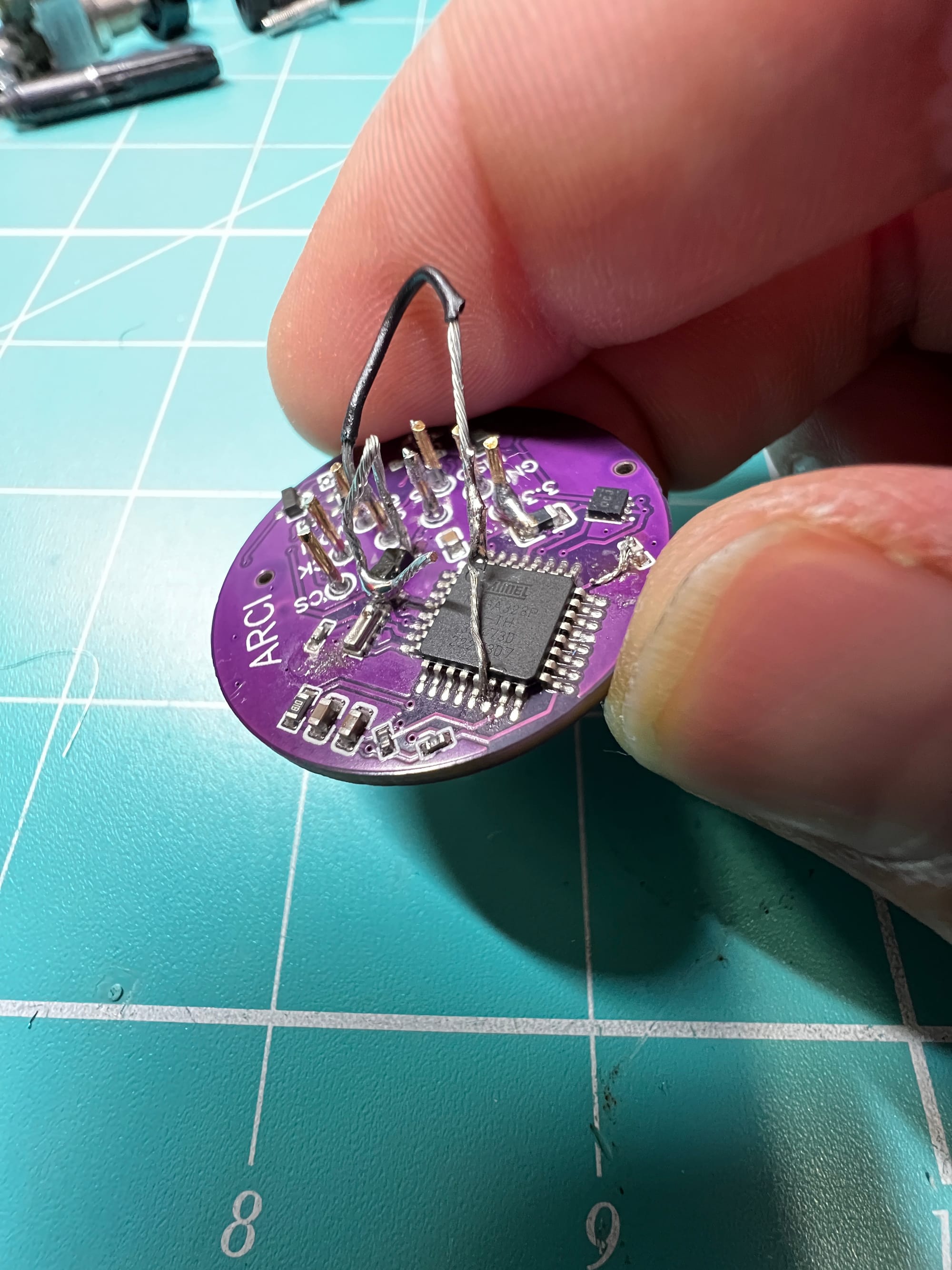
The Populated PCBs arrived WAY faster than I anticipated. I was expecting a turn around closer to two weeks, these were only 6 days including a weekend! So I excitedly installed the PCB pins and connected the USBasp programmer to the breakout pads and threw the sketch on.
As you can hear from my comment I was impressed with the result! 🙄 time to troubleshoot.
It was behaving the same as if the power was derping out again, so my first suspect was the power regulator - the one bit I was actaully worried about. Sure enough, I forgot a line, a pretty important one in fact. In the schematic, I skipped over a junction that joined the decouppled 3.3v line to the inductor for the 5v step-up regulator. The regulator uses the inductor as a current store before passing to the regulator. The regulator then uses the built up current in the inductor to boost the voltage up to the specified voltage. So basically the Arduino was not getting power and browning out in the SPI handshake again.
Quick trip to the schematic and PCB layout, adding the edit to the schematic (so I don't forget it) and a blob of solder to join the two pads I missed. Another attempt on the rig and same result...
Next culprit - the programming.
I didn't include a usb to serial chip due to the Atmega needing to be programed over the iscp pins anyway so I couldn't sit on the serial bus monitor watching for any output. I also didn't include any LEDs on the board since, again, no need for them past a confirmation that the board is powered up and I can confirm that with other methods.
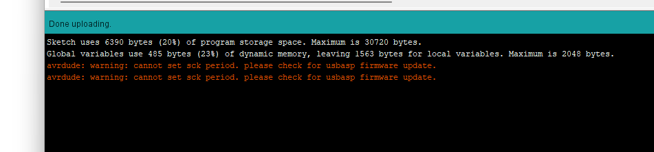
I noticed a warning popping up after I programed the board and went about resarching what it meant. I saw a lot of posts adding more information to the error message than what I was getting and prior symptoms that have no relation to what I was seeing - plus another post basically saying to ignore it. I decided to re-program the Arduino nano that I used as the POC and sure enough, the same message popped up. This was not the issue.
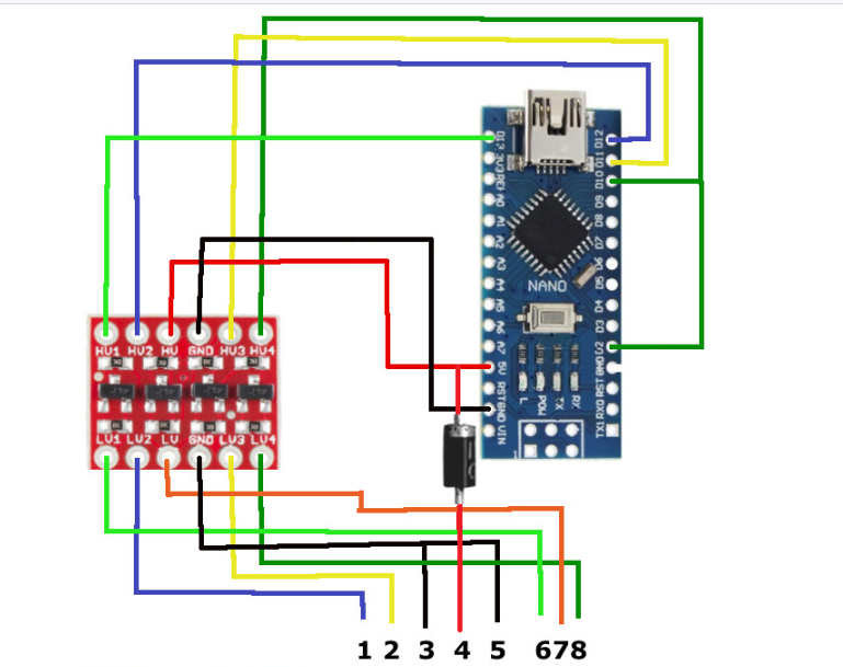
While I had the nano within arms reach I double checked the wiring and compared it to the code and the very crude diagram I used from an example I found in a Github comment. I saw a comment in the code that mentioned the D2 and D10 bridge being very important and sure enough I had connected the D2 side to ground. But this is on my working setup, according to the code - this shouldn't be working, however this was another line I had missed in my schematic entirely anyway. another 5 minute job with the soldering iron and another test.
Still nada....
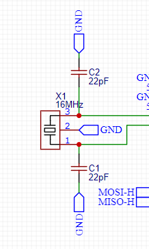
Back to the schematic, double checking all my paths, making sure I got the right parts installed from the fab - hang on. The 16mhz oscilator needs two load capacitors nearby, did I put one in the wrong spot? the 2 22pf caps are meant to be very close to the oscilator, as in the design specification says 'as close as possible to the crystal, and tracks as short as possible'. My dumbass put one of the caps on the other side of the arduino chip forgetting about this important design consideration...
Luckily I still have some patience left and a buttload of smd components in a box for me to try placing a cap closer to the oscliator. I would be putting a photo of that here but that bit fell off at some point in the night and I have no idea where it went but it also didn't work so, moving on.
Last ditch effort.
Moving to the later part of the night. I'm running out ideas past scrapping the batch and starting again from scratch with some more research into the parts I used and more careful consideration. The last time I confirmed power was an issue I had the nano plugged into USB before I plugged the unit into the wheelbase. So the arduino was already powered beforehand and ready to talk over SPI. I had an already cut USB cable sitting on the healing bench and soldered that on.
Same issue YET AGIN.... What's different!? what is stopping this thing from working!?
The diode.
As a safety I put a diode on the 5V line to stop the arduino from backfeeding into the wheelbase. This was omitted in the POC nano board after it kept breaking off the pin as I was moving it. I'll bypass the diode and try again, I said to myself this is my last change before I give up for the night. This is also when I realised the extra 22pf cap I put on the board was just missing, so I spent another 15 minues repairing the cut trace to the load cap over in africa.
YES! I said in my 'there are animals and people sleeping voice', aka I silently celebraded in my head and let out a huge sigh of releif. So turns out, the cap in afica is fine where it is, the D2 D10 connected together or D2 forgotten and D10 just pulled to ground just didn't matter in the slightest.
Forgetting a main power trace was a big oof on my part but thankfully an easy patch job for the first lot. Then the stupid diode getting me with the 0.8v drop on the 5v line. There's a momentary power swap/drop on either the 5v or the 3.3v lines that causes the Arduino to brown out and reboot sending the wheelbase into a failsafe mode and disconnecting. I was purely guessing at that point but it's issues like these is where an oscilloscope will be extremely handy. Maybe I need to setup a donation bin on here or the store so I can get myself these expensive tools...
Anyway.
It took several hours but I got there in the end, my creation works as expected, honestly, very surprisingly. While not perfect, needing some very minor changes and their housings (that are yet to be designed and printed), the first batch of the ARCI FFB enabler will be available to purchase from the ARabbidCow Industries store very soon.
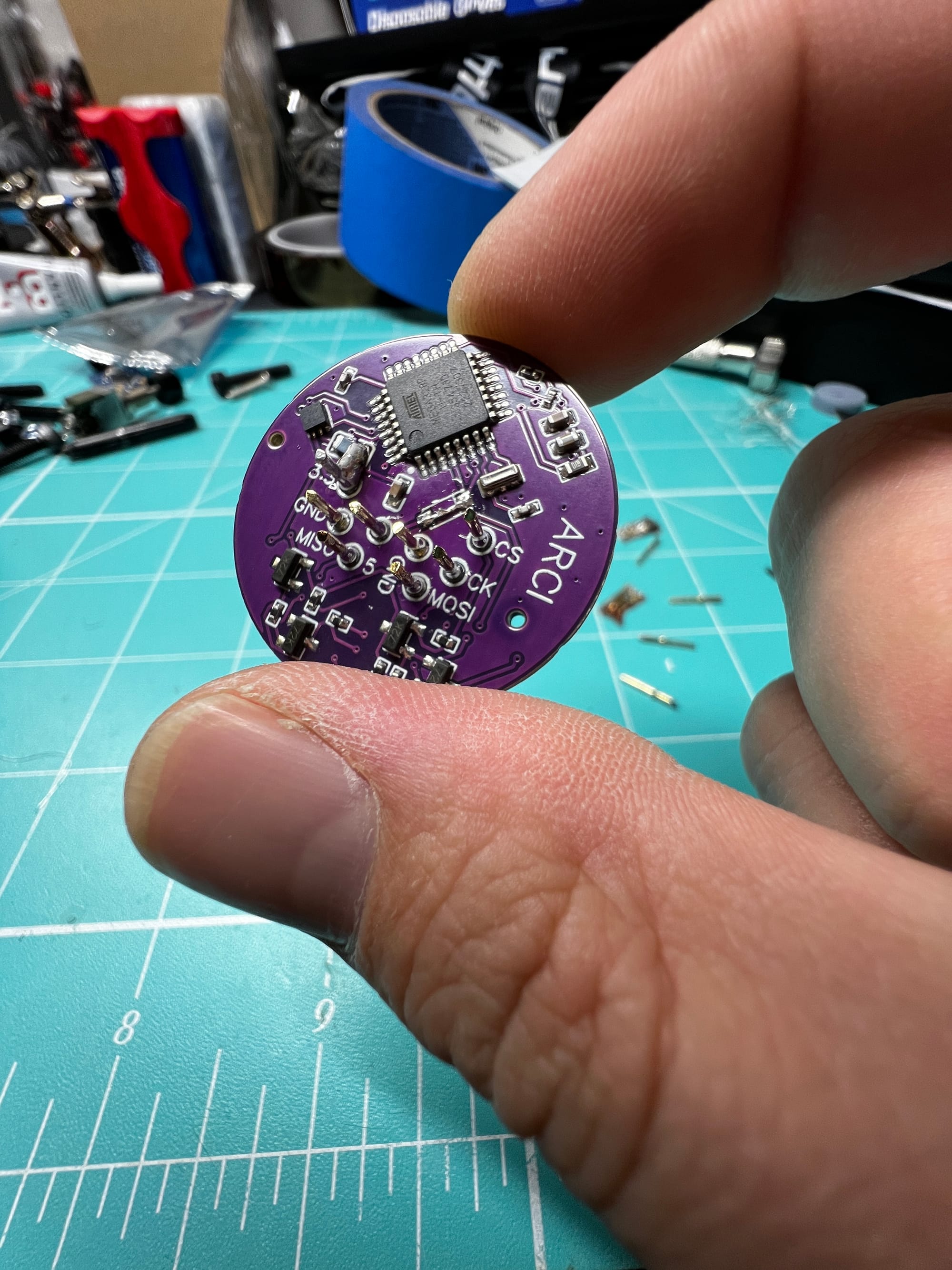
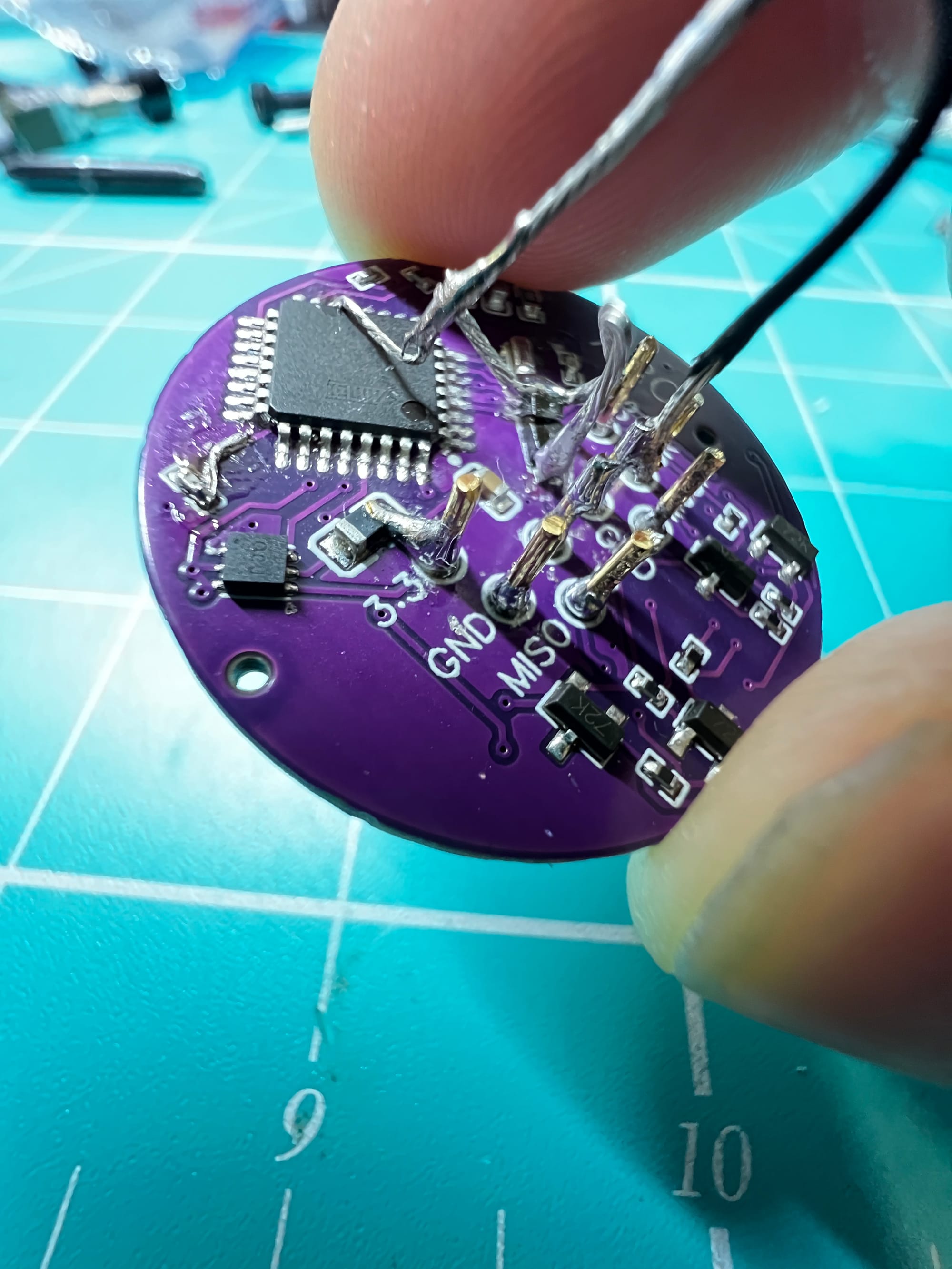
This is the 2nd board I finished assembling along with the adjustments needed.